Map matching
Introduction - what is map matching
The Map Matching component is responsible for determining where on the map to place the chevron.
Visually, it offers a cleaner user experience than displaying a raw location from the platform (e.g. GNSS, GNSS-INS, etc.): it can snap the chevron to the center-line of the road being driven, correct for inaccuracies in weak or unreliable signal, and smooth over discrepancies between the real world and the map used for navigation.
Functionally, it performs the vital role of translating raw location information into a format that is usable in the wider navigation context and the known road network—for example, determining what the speed limit is, whether the user should expect traffic, whether they have deviated from the planned route, or what their resulting ETA is.
This document details what inputs TomTom Map Matching requires to perform well—specifically, what enables it to accurately reflect the user’s actual location. It offers a breakdown of common use cases where relying only on GNSS is insufficient, and outlines what additional data is required, in what format, to achieve a correct result.
Use Cases - description of scope
This section defines the supported map matching use cases. Each use case is labeled with a descriptive title and a unique ID code, which is also used in the input requirements table below.
Basic functionality (UC0)
UC0 covers basic navigational functionality for GNSS-only systems. It defines the minimum set of fields that must be supported for map matching to function—these fields are strictly mandatory.
Map Matching is highly reliable in the following ideal conditions:
- The vehicle drives on well-mapped highways and B-roads, with road classes matching the vehicle profile.
- The environment is non-urban with an unobstructed sky view.
- Where the road network is not complex, and no specifically parallel roads are present.
- When the user does not deviate from the planned route—if one exists—and is not expected to perform unusual or complex maneuvers.
- When the vehicle is traveling at relatively high speeds.
However, when multiple of these conditions are not met, map matching performance may begin to degrade. In such cases, the algorithm attempts to compensate for inaccuracies in the received data. For example, when the GNSS signal is lost inside a tunnel, map matching activates Software Dead Reckoning—advancing the chevron along its previously known path to provide a seamless driving experience.
Automotive-quality map matching (UC1)
This is the use case for basic automotive quality map matching. It requires the same minimum inputs to be supported as UC0, but receives them from a sensor-fused GNSS-INS solution (INS stands for Inertial Navigation System, also referred to as Automotive Dead Reckoning).
By using an Inertial Navigation System, the vehicle is always able to provide some positioning information—even in the absence of a GNSS signal. When satellites are available, the system can further fine-tune its positioning data. As such, the quality of these inputs is generally higher than what a GNSS-only system can provide, and also more consistently available. This means the map matching component relies less on its internal algorithms to correct what might otherwise be considered bad data.
For example, Software Dead Reckoning—mentioned in UC0—will never activate for a system that already provides Automotive Dead Reckoning, because we can rely on this system to always provide input. As a result, the navigation experience is more accurate and stable compared to UC0, with less guesswork involved.
The fields required for UC0 and UC1 are also required for all subsequent use cases.
Note:
UC0 and UC1 represent the minimum requirements for all subsequent use cases. The fields they define are considered part of the core functionality of the map matching component.
UC0 and UC1 do not differ in scope, but in quality: GNSS-INS can be trusted to a greater degree than pure GNSS. Fewer corrections are applied to data received via GNSS-INS by the TomTom map matching algorithms.
To support UC1—and to distinguish it from UC0—integrators must provide at least one additional field. Supplying any data required by the other use cases listed in this document (i.e., UC1.1 through UC1.5) is sufficient. This signals to the map matching component that the input data can be treated with a higher degree of confidence.
Correct positioning in tunnels & urban canyons (UC1.1)
Required fields: All fields from UC1 + satellites.visible + satellites.used + distanceTraveled.value
Optional fields: distanceTraveled.error
UC1.1 covers cases of no or limited GNSS availability, such as in tunnels or some urban canyons.
The fields specified by UC1.1 are required for correcting the drift in input position that occurs naturally in the absence of (reliable) GNSS.
GNSS-INS systems, which integrate automotive sensor data but temporarily cannot calibrate it with GNSS, will provide position data that gradually drifts away from the vehicle’s actual position. In these cases, the increasing horizontalError will help the map matching component determine how much position (drift) correction needs to be applied. distanceTraveled helps determine the progress through the tunnel. The information about satellites helps determine when to apply this correction.
Correct vehicle heading displayed when reversing (UC1.2)
Required fields: All fields from UC1 + distanceTraveled.value + drivingDirection
Optional fields: distanceTraveled.error
UC1.2 covers the case of navigation while reversing. The expectation is for the chevron to move backwards, while still pointing in the same direction as the front (nose) of the vehicle.
When the fields required for UC1.2 are not provided, drivers may experience issues such as the perceived heading of the chevron flipping, the chevron getting stuck, or—worst case—the route being replanned, as the system may assume the car is somewhere else that matches its reported direction of travel.
Faster route deviation detection on highways (UC1.3)
Required fields: All fields from UC1 + lanesInView + drivenLaneIndex
Optional fields: turnLightIndicator
UC1.3 covers cases where the driven road contains multiple lanes that can be used to indicate where the driver will go—such as exits from highways.
When driving in areas where lane information is available in the map, integrating the required fields for UC1.3 enables faster or even instantaneous route deviation detection, route switching, or replanning. When these fields are not provided, or if there is insufficient map data, the map matching component is forced to rely on other indicators and may only detect and display deviations with a delay.
Lane Level Guidance (UC1.4)
Required fields: All fields from UC1 + lanesInView + drivenLaneIndex
Optional fields: -
UC1.4 covers cases of Lane Level Guidance—being able to show the driver, at lane level, where they are and where they need to be to continue along their planned route. This provides significant value for complex maneuvers involving multiple lanes.
It requires a perception system capable of relaying information about the vehicle’s current lane, as well as lane-level data availability in the map.
Correct vehicle position on stacked roads (UC1.5)
Required fields: All fields from UC1 + pitch.value
Optional fields: lanesInView + drivenLaneIndex + pitch.error
UC1.5 covers cases of stacked roads (also known as “3D roads”)—where multiple roads overlap and share similar latitude and longitude, but differ in altitude.
Since altitude is difficult for satellites to estimate accurately, the key input for supporting UC1.5 is the vehicle’s pitch data. Matching the pitch to the slope gradient of nearby connected roads is often the most effective way to help the navigation system distinguish between on-ramps, off-ramps, and parallel roads in complex multi-level road environments.
Required inputs – breakdown per use case
The table below details the fields required to support each use case. Fields from UC0 and UC1 form the baseline and must be supported for all subsequent use cases.
When a field may be reported as null, its value is considered optional—however, providing accurate values will improve overall performance.
In the table:
🟢 Green circle indicates a mandatory field (required to support the use case).
🟡 Yellow circle indicates an optional field (not strictly required but may improve performance).
| NavSDK Field | Description | UC0 | UC1 | UC1.1 | UC1.2 | UC1.3 | UC1.4 | UC1.5 | Input expectations | Impact of bad data |
|---|---|---|---|---|---|---|---|---|---|---|
| location.position.point.latitude | Latitude value in degrees [-90.0, 90.0] | 🟢 | 🟢 | 🟢 | 🟢 | 🟢 | 🟢 | 🟢 |
|
|
| location.position.point.longitude | Longitude value in degrees [-180.0, 180.0] | 🟢 | 🟢 | 🟢 | 🟢 | 🟢 | 🟢 | 🟢 |
| |
| location.position.horizontalError | 1-sigma horizontal error in meters, or null | 🟢 | 🟢 | 🟢 | 🟢 | 🟢 | 🟢 | 🟢 |
| |
| location.velocity.speed.value | Vehicle speed over ground (GNSS) in m/s; 0 at standstill | 🟢 | 🟢 | 🟢 | 🟢 | 🟢 | 🟢 | 🟢 |
|
|
| location.velocity.speed.error | 1-sigma speed error in m/s, or null | 🟡 | 🟡 | 🟡 | 🟡 | 🟡 | 🟡 | 🟡 |
| |
| location.time.utcMilliseconds | UTC fix time incl. leap seconds (ms) | 🟡 | 🟡 | 🟡 | 🟡 | 🟡 | 🟡 | 🟡 |
|
|
| location.time.monotonicNanoseconds | Monotonic timestamp of fix (nanoseconds); must use a single clock | 🟢 | 🟢 | 🟢 | 🟢 | 🟢 | 🟢 | 🟢 |
|
|
| location.attitude.course.value | Heading over ground (0–360°, relative to North); GNSS/INS value must freeze at standstill | 🟢 | 🟢 | 🟢 | 🟢 | 🟢 | 🟢 | 🟢 |
|
|
| location.attitude.course.error | Course error (1-sigma), or null | 🟡 | 🟡 | 🟡 | 🟡 | 🟡 | 🟡 | 🟡 | ||
| location.provider | Enum: Gnss, GnssIns, or Network; GnssIns extends Android provider set | 🟢 | 🟢 | 🟢 | 🟢 | 🟢 | 🟢 | 🟢 |
|
|
| location.position.altitude.value | Altitude above ellipsoid (WGS-84/GCJ-02), meters [–20000, 20000], or null; unused for UC1.5 |
|
| |||||||
| location.position.altitude.error | Altitude error (1-sigma), in meters; or null | |||||||||
| location.satellites.visible | Number of visible satellites [0–999], or null | 🟢 |
|
| ||||||
| location.satellites.used | # of satellites used to fix [0–999]; class should be null if unknown | 🟢 |
| |||||||
| location.distanceTraveled.value | Distance since last update in meters (if enabled) | 🟢 | 🟢 |
|
| |||||
| location.distanceTraveled.error | 1-sigma distance error since last update, in meters; or null | 🟡 | 🟡 | |||||||
| location.drivingDirection | Driving direction: 0 = FORWARD, 1 = REVERSE (nullable) | 🟢 |
|
| ||||||
| location.turnLightIndicator | Turn signal: 0 = OFF, 1 = LEFT, 2 = RIGHT, 3 = HAZARD; or null | 🟡 |
|
| ||||||
| location.perception.lanesInView | number of drivable lanes detected in direction of travel; >0 if enabled, else | 🟢 | 🟢 | 🟡 |
|
| ||||
| location.perception.drivenLaneIndex | Index of current lane (0 = leftmost, direction of travel); ≥ 0 if enabled, else | 🟢 | 🟢 | 🟡 |
| |||||
| location.attitude.pitch.value | Pitch angle (–45° to 45°), rotation around y′-axis of intermediate Navigation frame; or | 🟢 |
|
| ||||||
| location.attitude.pitch.error | Pitch error (1-sigma), in degrees; or null [*] | 🟡 | ||||||||
| location.attitude.yaw.value | Yaw angle (0°–360°), rotation around z-axis of Navigation frame; or |
|
| |||||||
| location.attitude.yaw.error | Yaw error (1-sigma), in degrees; or null [*] | |||||||||
| location.attitude.roll.value | Roll angle [–180°, 180°], rotation around x″-axis of intermediate Navigation frame; or |
| ||||||||
| location.attitude.roll.error | Roll error (1-sigma), in degrees; or null [*] |
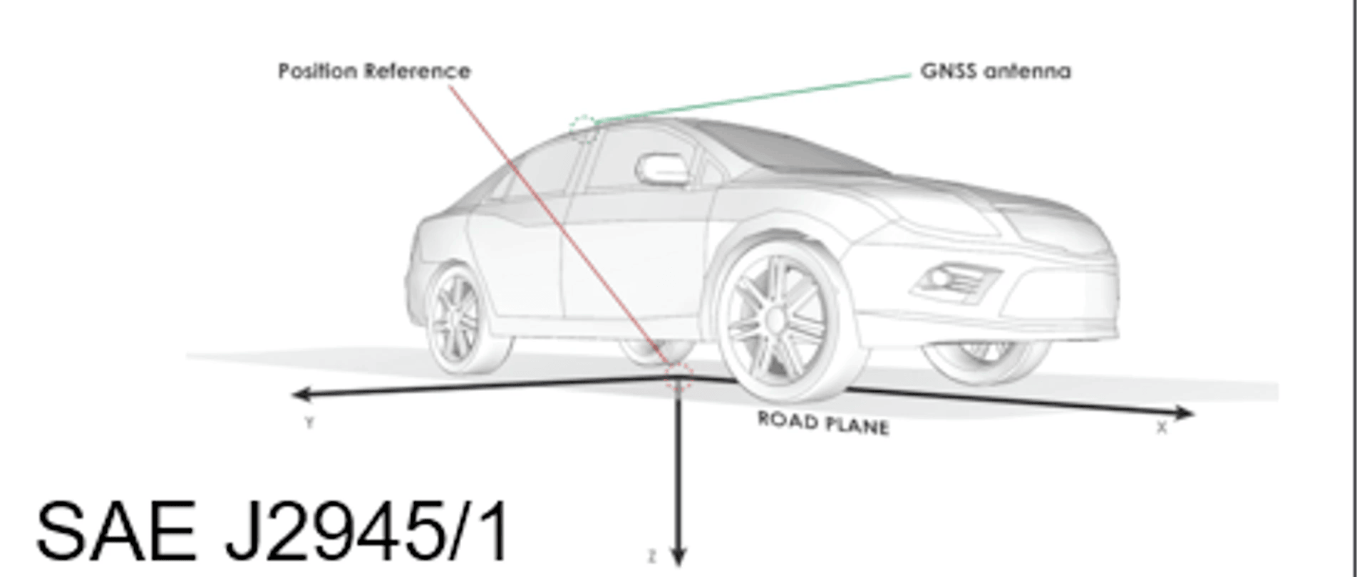
[*] Attitude class and rotation order
The Attitude class defines yaw, pitch, and roll rotation angles from the local Navigation (North East Down – NED) frame to the vehicle/body coordinate system, following the z–y′–x″ rotation order. The body frame is defined as follows (see also SAE J670e / SAE J2945/1):
- The x-axis points toward the front of the vehicle.
- The y-axis points toward the right side of the vehicle.
- The z-axis points downward.
The rotation order is defined as follows:
-
Yaw: Rotate the navigation frame axes xn and yn around the zn axis by the yaw angle.
→ This results in an intermediate reference frame with axes x′, y′, z′, where z = zn. -
Pitch: Rotate the x′ and z′ axes around the y′ axis by the pitch angle.
→ This results in another intermediate frame with axes x″, y″, z″, where y = y′. -
Roll: Rotate the y′ and z″ axes around the x″ axis by the roll angle.
→ The resulting frame after all three rotations is the body frame.